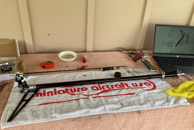
If you follow my site or my Face Book page, you know that I left Gaui and started a new chapter with Miniature Aircraft. Well... my first MA kit arrived a couple days ago, and I started building it this morning (April 17, 2021).
The build was very straight forward, but also very technical. Not a hard build, but definitely not a kit which can be just "slapped together". There are a lot of steps which must be done perfectly, to avoid issues later, such as getting the proper gear mesh between the crown gear and the torque tube gear. Sounds scary, I know. But follow the build manual to the letter, and it will all be fine.
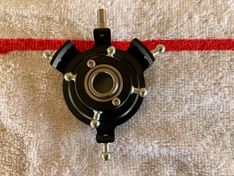
The first step in the build was installing the link balls in the swash plate. There are two sets of holes in the swash plate for the two front servos, so you must pay attention to which ones the link balls will go into. The two rearward holes are the ones you want.
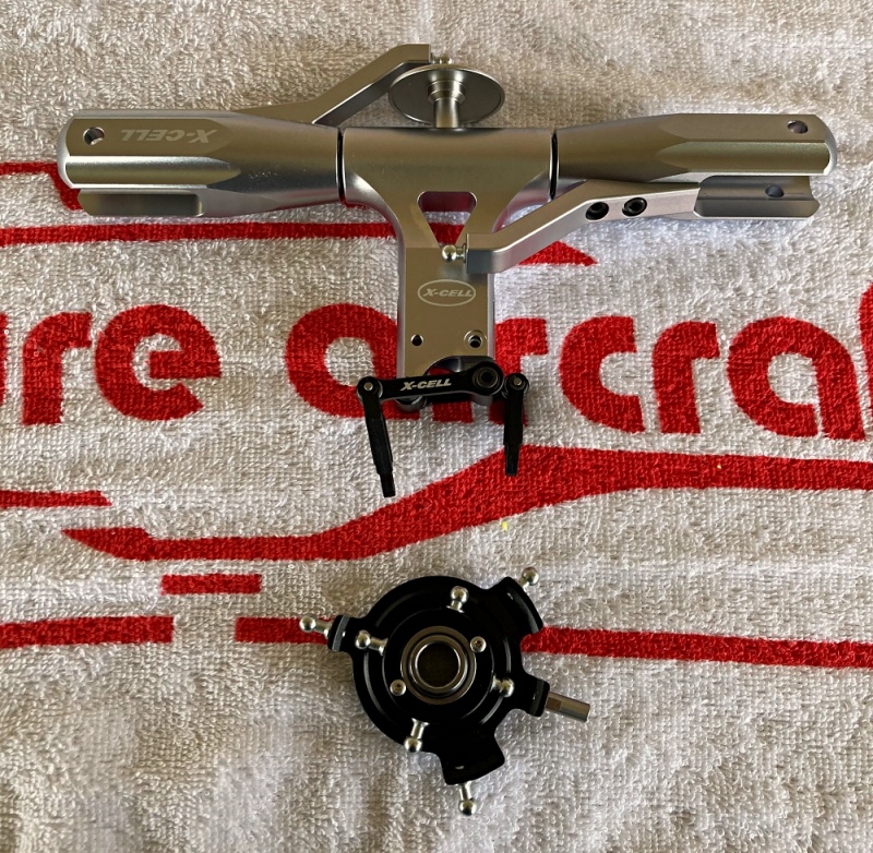
Moving on to step number two..... Head assembly! The first thing I noticed about the head components, was the head dampers. Instead of the usual rubber grommet style dampers, they used machined plastic (it feels like delrin) and O-rings. Pretty cool design and it makes for a solid feeling rotor system.
*Build tip* I found it very difficult to hold the damper sleeve to install the O-ring into the groove in the sleeve. I put the sleeve on the end of the spindle shaft, and I was able to control the sleeve and get the O-rings installed.
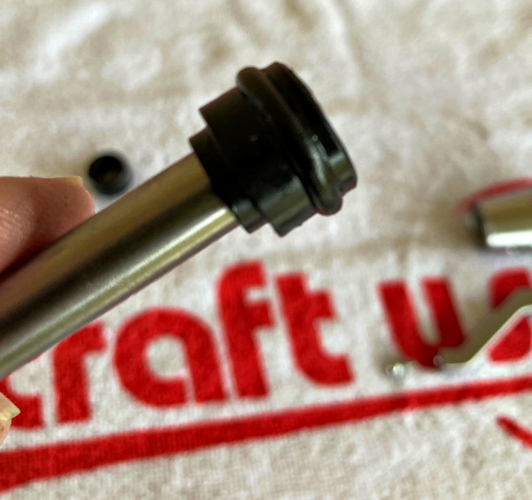
The rest of the head assembly was pretty must as it is with any kit, and it went together perfectly. One thing I want to mention, is that the spindle shaft has a nice slip fit into the damper sleeves and slides in with no effort.

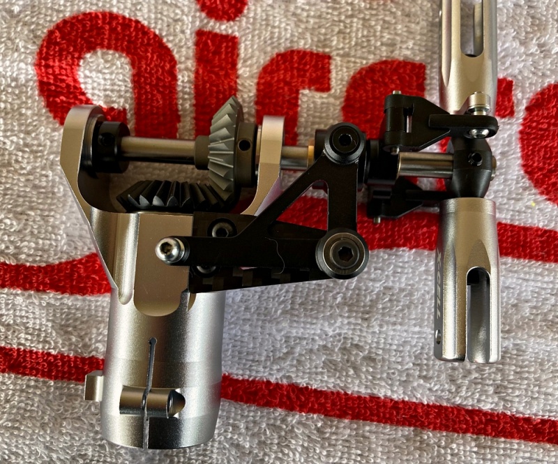
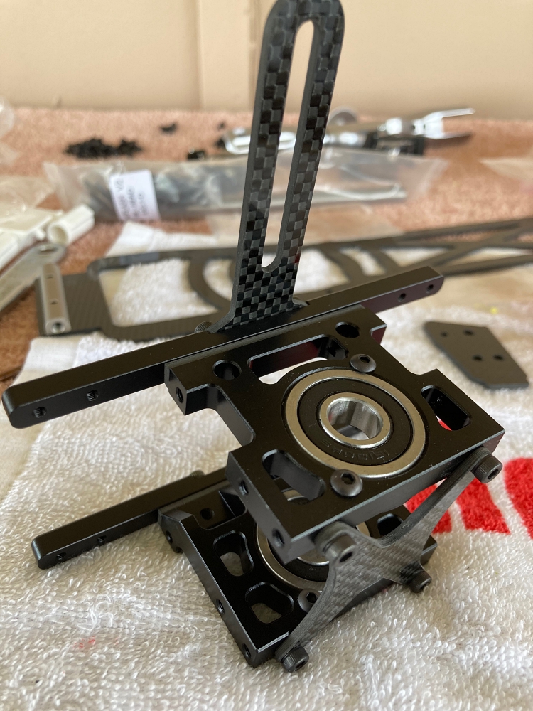
Next we move on to the tail box. The tail box on this helicopter is the most impressive I have ever seen. It`s machined out of one piece of aluminum, and it`s just gorgeous.
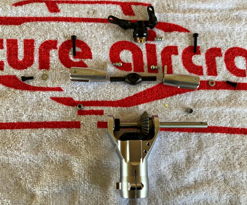
The tail output shaft, gears, and bearings in the tail box and tail blade grips are all factory assembled. So that saves a few steps in the build. The slider, and tail rotor assembly is pretty basic stuff. The main thing to look out for is making double sure that the bog point socket screws in the tail hub, (0056) are seated properly into the dimples in the tail output shaft. Not doing so can cause serious issues later.
Moving on to the tail boom mount. The way the tail boom is mounted is very different from what I have seen in other brands. It`s amazingly simple, and maintenance friendly.
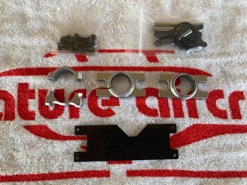
The tail boom mount is simple, but you still have to pay attention when assembling it. The carbon fiber plate (131-128), can easily be installed backward, which will result in misalignment and improper fit.
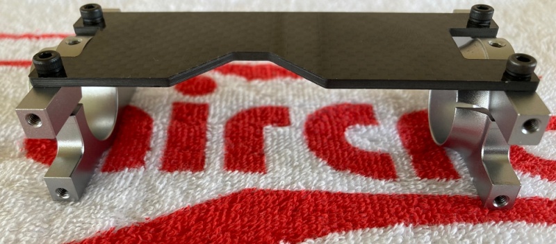
Once this step is done, it`s time to install the tail boom. The end of the boom with the hole closest to the end, slides in until the hole lines up with the screw hole in the center of the mounting clamp (128-80). Once lined up, an M3x6 socket screw is installed to pin the boom. Then the pinch bolts are tightened. Be sure not to over tighten the pinch bolts, to avoid damaging the tail boom.
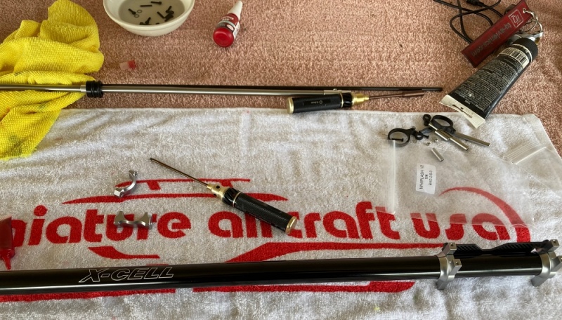
The torque tube is one of the tricky parts of the build, and the manual MUST be followed to the letter here. Otherwise, the bearings can slip and come out of the torque tube sleeves. I assembled my torque tube the night before starting my build, so that the bearing retainer would have ample time to cure before inserting the torque tube into the boom.
*Build tip* When installing the screws into the ends of the torque tube, I like to install them in opposite directions from each other. Meaning... The socket heads of the screws are opposite sides of the torque tube from each other. In my opinion, this can keep tail vibrations down...due to an out of balance torque tube. This may or may not be the case, but it something that I personally like to do. :)
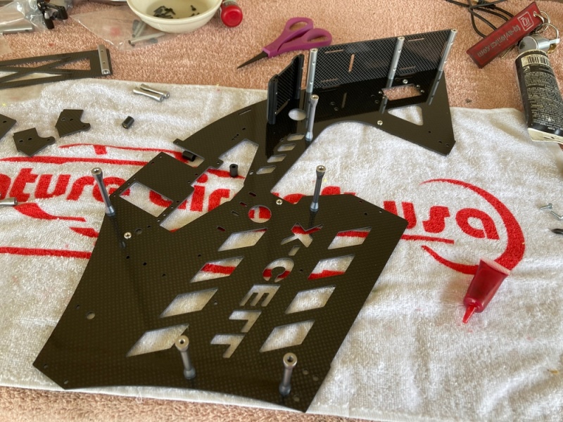
The frame assemble was a lot of fun for me. The quality, fit, and finish kept me smiling through the entire build. Before I got going on the frame assembly, I sanded the edges of all of the carbon fiber parts, as per the manual, so that there were no sharp edges anywhere that could damage my wiring. I did use an N95 particle respirator, a face shield, and nitrile gloves while doing this. Plus I was outside with the wind at my back. Safety first, right? ;)
Assembly of the frames as mentioned above, was a LOT of fun and I took my time and savored the moment. The bearing blocks are beautifully machined and finished. As are all other components of this kit.
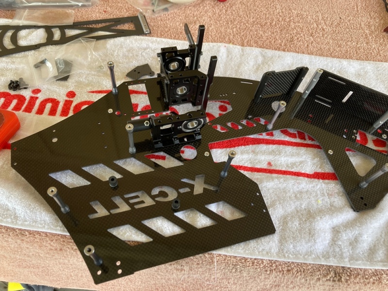
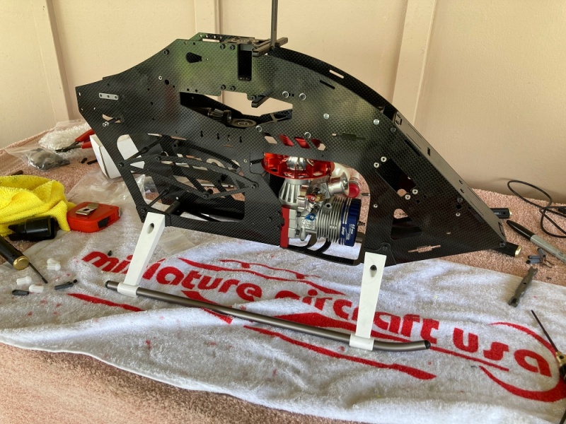
The frames went together nicely, and I soon found myself ready to install the engine. My engine of choice is the OS 105 HZR DRS, with a Botos Pro tune pipe.
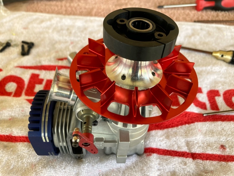
Something else I thing is worth a mention, is the was the fan shroud mounts. On the Whiplash, the shroud can be removed WITHOUT having to remove the engine. How cool is that? remove four screws and it comes right off. Speaking of the fan. WOW.... this thing is beautiful! The intricate machining, and that bright red anodizing is just incredible.
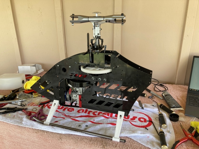
Once the engine was installed, I moved on to installing the landing gear, tail boom and tail struts. All that`s left now, is installing the electronics and getting it set up to fly. Which will be in part two of the build in the next day or so.
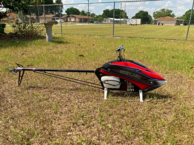
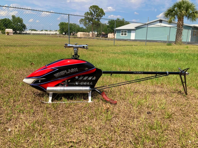
That`s it for now. I will get the electronics in and post the second part of the build as soon as I can. Thank you all for visiting my site, and have a wonderful day. :)